Not sure if this is exactly the right place to ask this question. If not, mods please put it where it should be. Anyone else.
HELP!
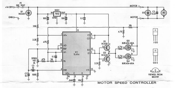
I have an electric billy cart with a dead controller board. I constructed the kit circuit below to replace the dead board and it works well enough for the job except for one small problem. The throttle on the billy cart utilizes a hall effect device and not a pot.
The billy cart also has a handbrake with a switch that closes when applied. I use this with a resistor to discharge C2 and pull pin 4 (inhibit) high. This ensures a gentle start (as the capacitor slowly charges through the 100k resistor) if the brake is released with the throttle advanced.
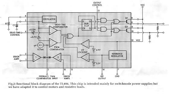
The output range of the throttle is 950 mV to 4.1 V if V
REF (5V) is used as the supply. (Essentially dropping it in in place of the pot.)
4.1 V is sufficient to achieve the maximum 90% duty cycle of the chip, but 950 mV leaves me with a minimum duty cycle of about 21%, and of course a motor that won't stop.
I think an AA cell between the circuit ground and throttle ground might do the trick, but 1) I'm not sure what effect a negative voltage applied to the circuit might have; and 2) 6.5 Volts exceeds the recommended (though not the absolute) max supply voltage of the hall effect device. 6V & 8V respectively. And I'm not even positive about these figures as I can't get the actual device out to read the part number. (I'm using the datasheet for the UGN3503 as a reference.)
I'm also going to suffer from a significantly reduced top speed unless some of the resistors are changed. Which ones? And what should the new values be?
Can anyone confirm whether this would work, or suggest a different modification to the circuit that would allow me to use the hall effect throttle?